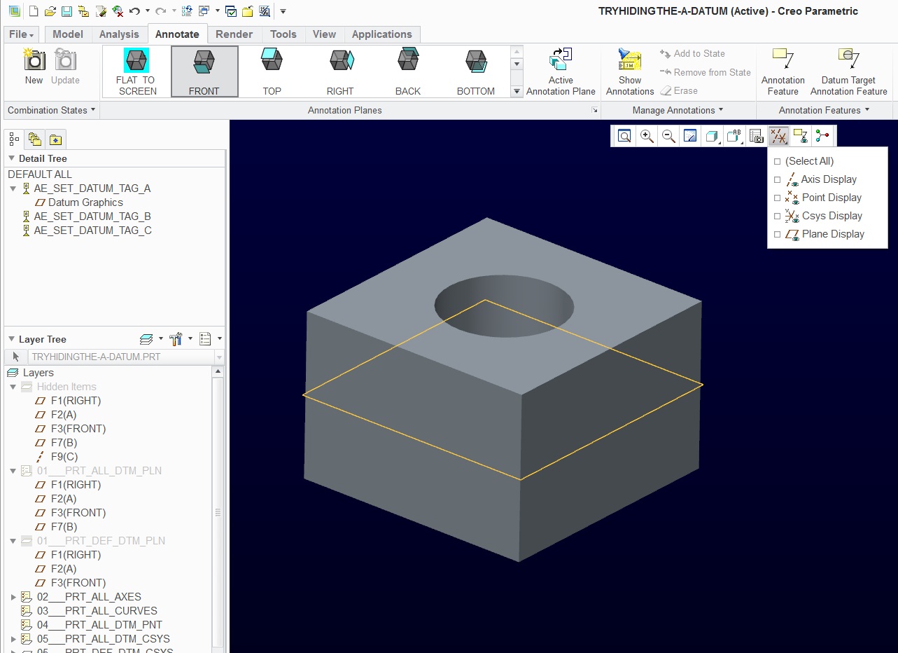
So the "proper" method already mentioned in this thread is to put your sketches or cosmetic sketches on layers that can be blanked or shown on a per-view basis. 0:00 / 7:22 Creo Parametric - Sketch Mode - Sketch References Creo Parametric 26.9K subscribers Subscribe 4.9K views 4 years ago Creo Parametric - Sketch Mode This Creo Parametric. Unfortunately, that is not a great solution if you have threaded holes and you do want the cosmetic threads to stay shown in the view!

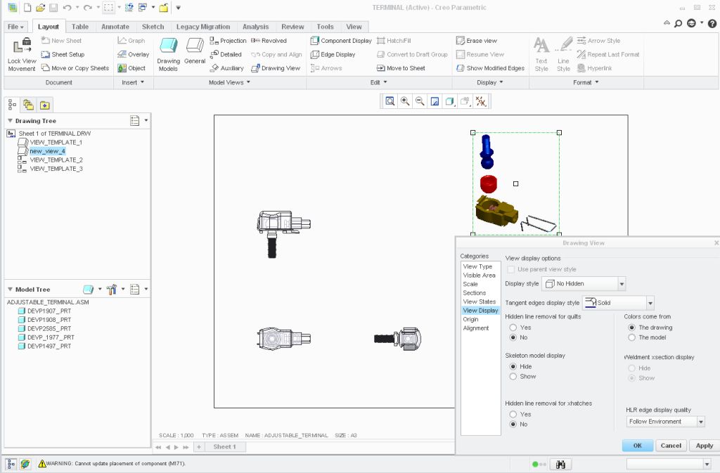
So that's one way to control the visibility of cosmetic sketches and s o that can be an answer to your first Q. One more thing about cosmetic sketches - you can right-click on a view and "erase/show cosmetics". But why use such a hack when a regular sketch can suffice? You can tilt the sketch plane about 0.1degrees and get a decent looking result. This answers why your cosmetic sketches are not showing up on any orthogonal projection views. If you open an Inventor, Pro/ENGINEER, or Unigraphics file that has missing. They are very handy when you are dealing with non-parametric things such as logos and labels that contain a lot of entities because you can use the "under-constrained" mode and essentially doodle something without the system crawling to a stop trying to solve all the sketcher constraints!Īnd another thing I learned during this investigation, is that cosmetic sketches they are drawn on a plane that is orthogonal to the view plane will not be shown in that view. Use the Save As command to export parts, assemblies, drawing sheets. So cosmetic sketches are a bit of an oddball and perhaps it is wise to avoid them. Now the long winded answer to your first Q: If set to "total" (default), then only things entirely in front of the cutting plane will be removed from view. If set to "trim", then system removes from display the portion of datum curves and cosmetic features that is in front of section cutting plane. (in drawing mode, file->prepare->drawing properties->detail options (change)->find->(search descriptions)->type keyword "cosm"->find now) So for your second Q, this drawing option seems promising: this course designed in such a way that you will learn about all important tools and commands of the software.This is a streamlined course to take you from knowing nothing about creo to give you all the. In 2010, the company has changed its name to creo parametric.
ADD A TEXT SKETCH IN CREO PRO E SOFTWARE
So I investigated some things in my setup (Creo 3.0 M130) Pro Engineer (pro/E) is 3D CAD/CAM/CAE software developed by PTC corporation. This shows the symbolic names of each feature.Hello! from your descriptions, y ou seem to say that your work and home setup produce different results - namely that at home, your sketch is not shown in the section view (screenshot) while at work it is shown. To find the feature name, click Model Intent > Switch Symbols (Fig.In the example below, we’ll vary the drive size, that is, the extruded fitting that attaches to the wrench handle. This paper presents a preliminary comparison between the role of computer-aided design (CAD) and sketching in engineering through a case study of a senior design project and interviews with industry and academia. Identify a feature you want to modify for your variants.

Change the name to whatever you wantto name your part and hit OK. Next hit the NewButton, make sure the type is set to part.

WebTo add text to the dimension value, such as diameter, ref, type. You can apply this concept to bolts, washers, or even larger assemblies, saving yourself loads of time and disk space. Creo Parametric - 7.0, 8.0, creo drawing red dimension mean DIFFERENCE BETWEEN.

With table-driven design, every row in your table produces a different variant of the generic. Rather than model and save each piece separately, you can create a generic socket in PTC Creo, and then use a Family Table to quickly create variants of the generic by changing just the relevant dimensions or parameters. For example, think of a collection of socket wrenches ranging from 0.25 to 1 inch. Create a vertical line, starting at the bottom point to choose text placement and height. Accordingly,how do i add text in 3d creo Within the sketch environment, click the text icon in the sketching group. Suppose you want to design a group of similar products that vary only slightly from each other. To enter text, under Text, select one of the following: Enter textType a single line of up to 79 characters of text.


 0 kommentar(er)
